
`
![]()
![]()
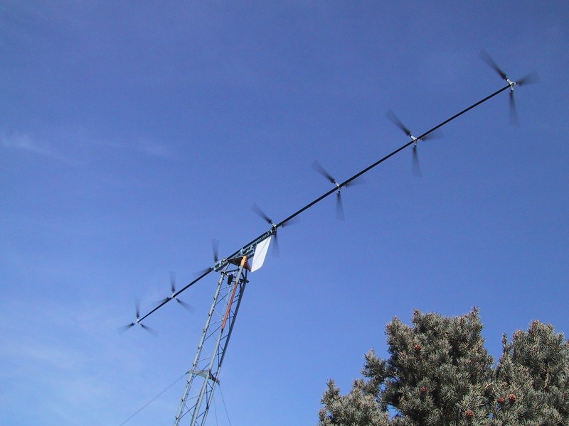
Latest Selsam Wind Turbine Sets World Record!
More Rotors = More Power. 6000 Watts from a 7 foot diameter turbine.
Currently funded by The California Energy Commission
http://www.energy.ca.gov/contracts/smallgrant/2003-02-21_awards_02-02.html
U.S. Patent Numbers 6,616,402 and 6,692,230 and other patents pending including U.S.and international (PCT) around the world http://www.uspto.gov
5300 watts at 32.5 mph one minute average with no furling - translates to 6000 watts at sea level
Latest Data Confirms the Immense Power-Gathering Ability of the Multi-Rotor!!! More Rotors = More Power!!! See newly-generated power curves below:
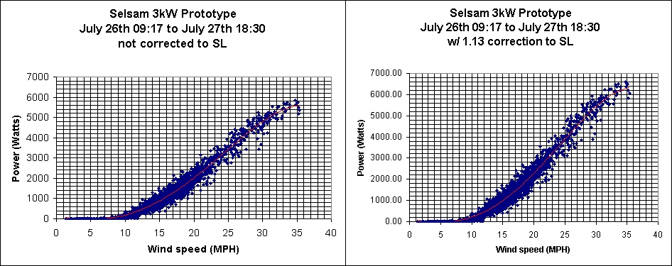
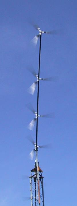
6000 watts at 32.5 mph when corrected for sea level (right). Raw data is at left. Sea level data are: 5400 watts at 30 mph; 4000 watts at 25 mph, over 2000 watts at 20 mph, and over 1000 watts at 16 mph. Data was taken at one minute averages at 5000 feet elevation at windtesting.com in Tehachapi, CA in
July 2004. Diameter is 7 feet. Tower height is 60 feet. Anemometer placed at height of 3rd rotor from the front, on a separate tower about 50 feet from prototype tower. Note that even uncorrected for sea level, we get a solid average 4000 watts at 27 mph at 5000 feet elevation. Low windspeed performance is superb. We get the same power at half the windspeed of a normal turbine,
for the same diameter, because we have more rotors. At the same speed, we get six (6) times the power(!), by adding six additional rotors behind the first. Rotors are placed out of the wake of preceding rotors in order to receive fresh wind. A total of 21 blades are well placed to receive fresh wind and turn a common generator - Total moving parts: 1
![]()
Staggeringly enhanced output, or 5 to 6 times the power, is achieved by the addition of multiple, co-axial rotors.
Here was the previous power output at a lower voltage in May 2004:
New Selsam Monster Turbine funded by The California Energy Commission
http://www.energy.ca.gov/contracts/smallgrant/2003-02-21_awards_02-02.html
shatters world record for power output of a 7 foot diameter turbine:
5033 watts@ 31.81 mph; 3961 watts@ 26.1 mph; 2464 watts@ 21.19 mph; 1943 watts@ 18.9 mph
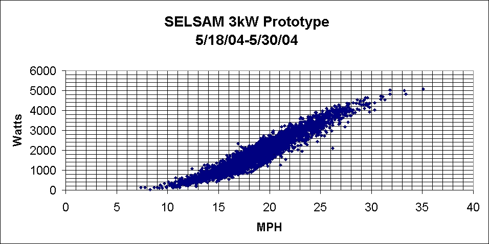
Power Curve taken over a 12-day period in late May, 2004 at Windtesting.com in Tehachapi, CA
1000 watts at 16 mph
2000 watts at 20 mph
3000 watts at 24 mph
4000 watts at 27 mph
5000 watts at 33 mph
3961 watts at 26.1 mph one minute average with no furling - translates to 4000 watts at 27 mph
To correct for 5000' altitude add ~13% to yield about 4500 watts at 27 mph!
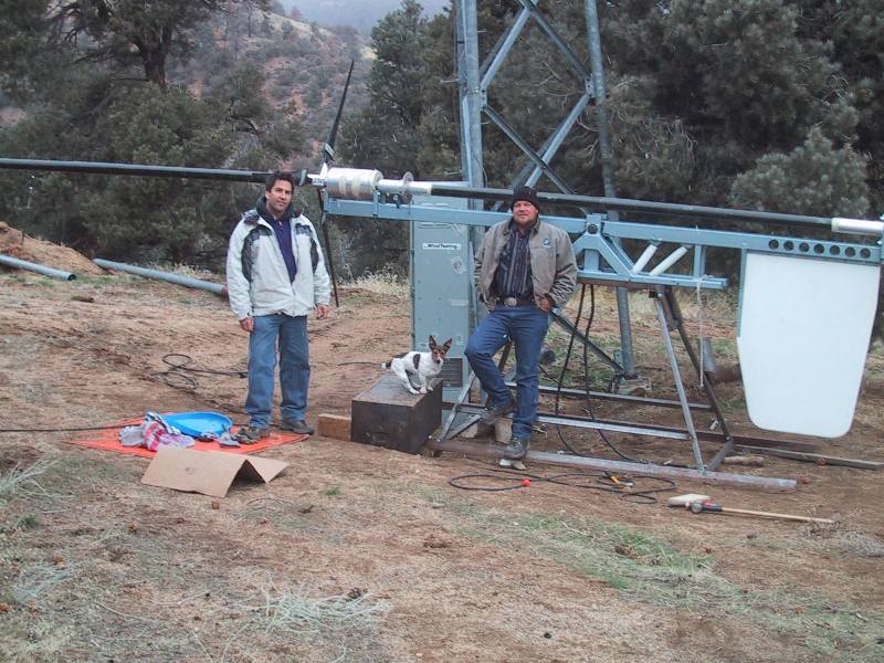
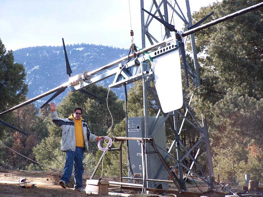
Brent Scheibel, Founder of Windtesting.com adjusts furling speed by changing gas springs.

The awesome machine reaches into the sky, grabs all the power it can, and SLAMS it into the generator! A single 7 foot diameter rotor would not even turn this powerful generator.
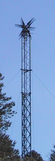
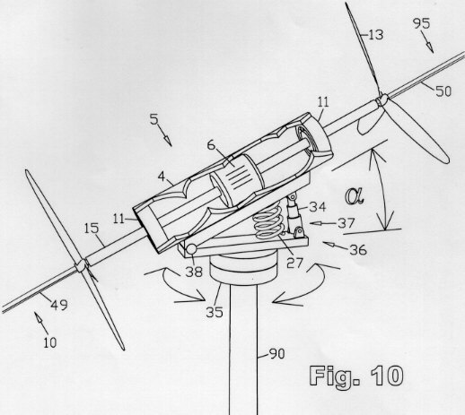
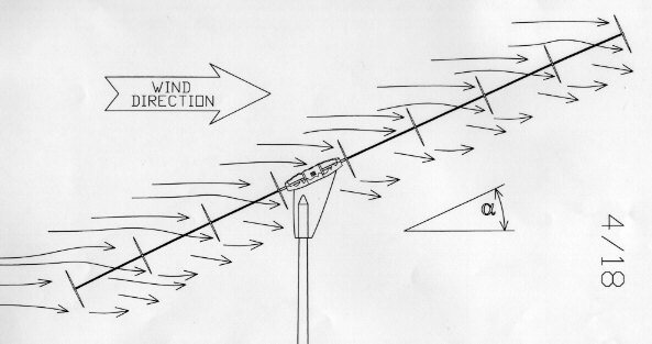
The wind sees a profile of one seven foot diameter rotor at high wind speeds, extended into the third dimension. At lower wind speeds, more swept area is exposed, at higher windspeeds, less swept area is presented to the wind. The angle relative to the wind is automatically adjusted depending on wind speed.
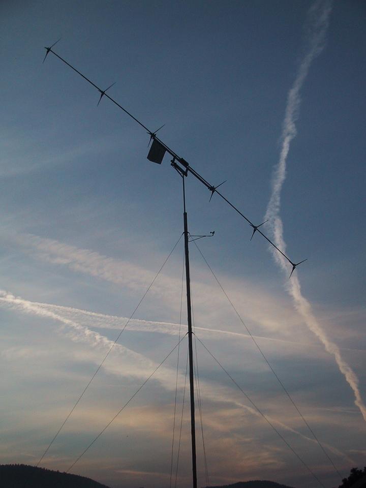
A true side view in the normal operating (non-furled-back) position. It is offset at angle alpha to the wind direction. All rotors are individually exposed to a fresh stream of wind, substantially undisturbed by upwind rotors. In this case the offset angle is in the vertical plane.
At 15.38 mph, 910 watts, 10 minute average
At 16.94 mph, 1071 watts, 10 minute average
At 20.94 mph, 1822 watts, 10 minute average
This is the answer to low wind speed performance - the long-sought "low wind speed turbine" We get the 1000 watt performance of a 7 foot diameter single-rotor turbine at about half the wind speed. Which is saying a lot 'cause the power in the wind is a function of the wind speed cubed.
Note that this is at 5000 feet altitude, where the air is thinner, and the machine was set for furling very early (low speeds) at the time this data set was taken.
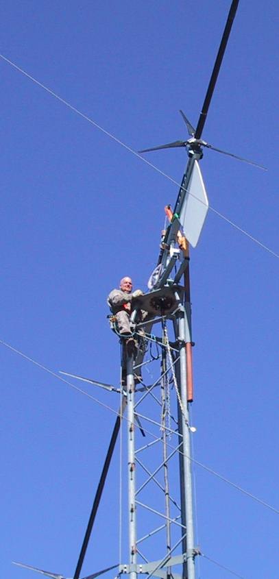
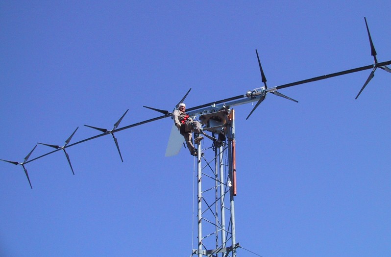
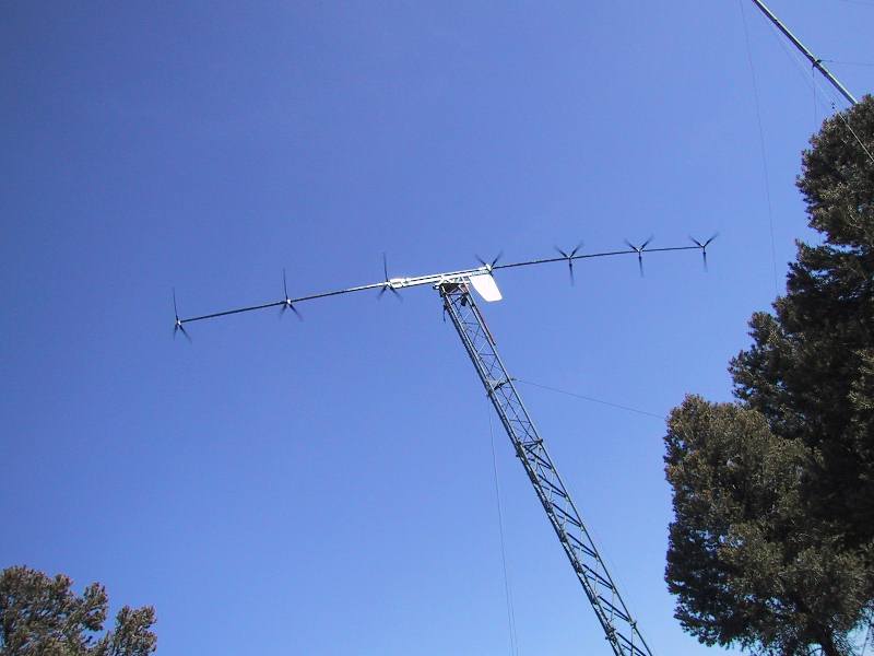
Brent Scheibel installs 7 rotor turbine atop tower at Windtesting.com in Tehachapi, CA
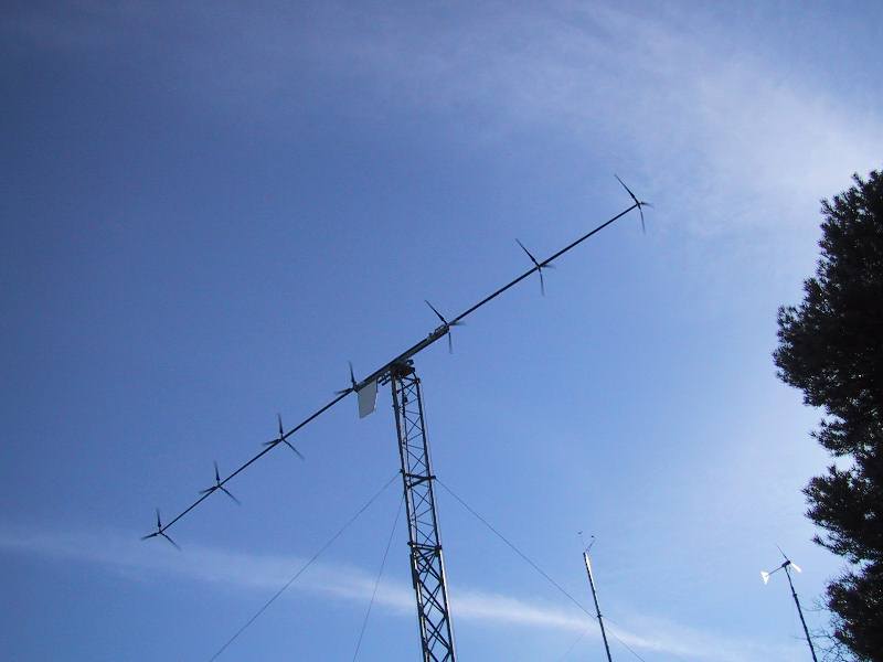
Seven rotors or one rotor - same diameter - same rpm - which turbine produces more power?
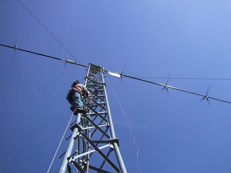
Looking up from base of tower, that's Doug
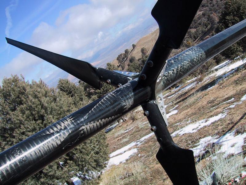
Carbon fiber driveshaft, aluminum hubs, carbon-reinforced polypropylene blades
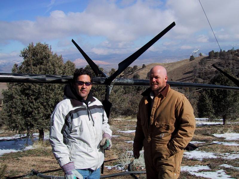
Doug, Brent, and Ezra the aerodynamic dog, pose for the camera with record-setting turbine.
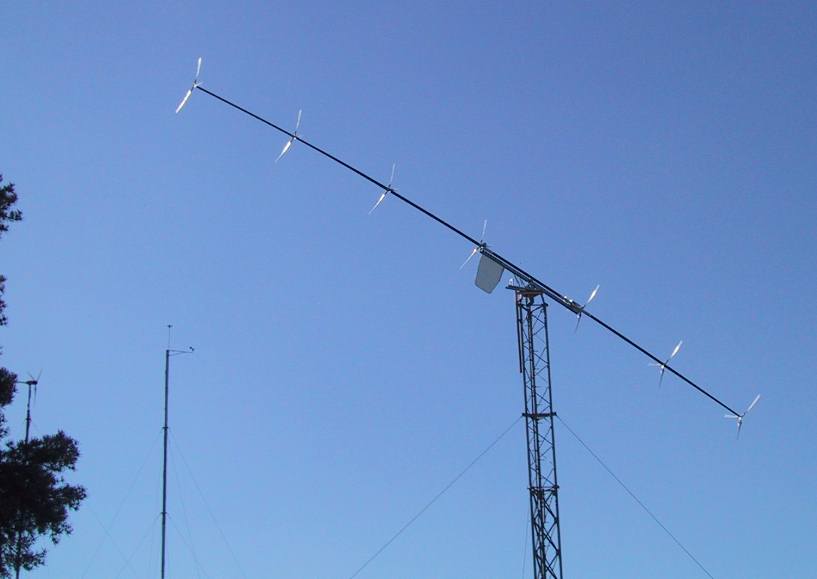
Zingin' along on a sunny spring day...
Doug and Brent hangin' with the turbine at ground level in late winter 2004 at Windtesting.com in Tehachapi, CA
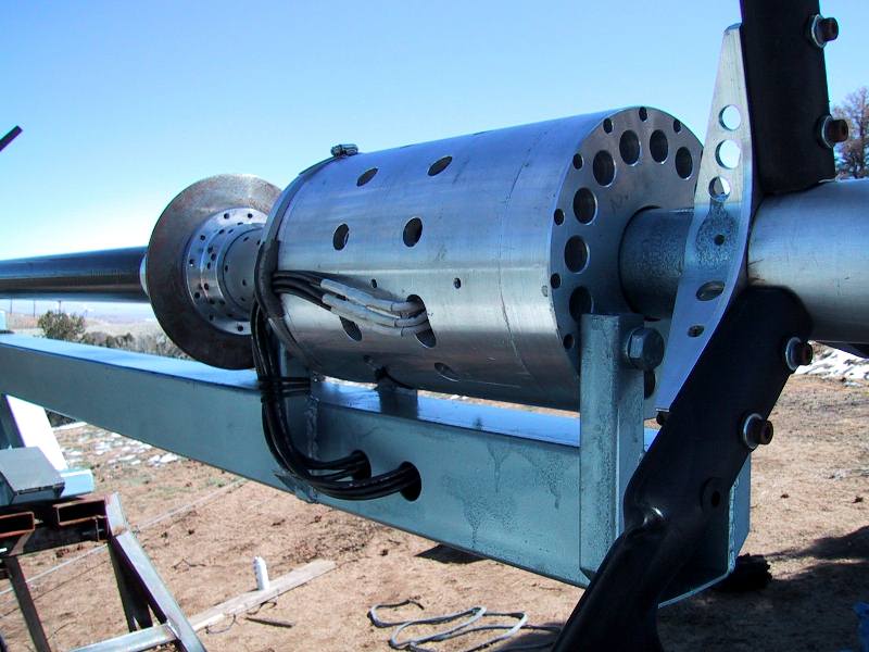
Dual three-phase alternators feed power to rectifying diode sets below. Hydraulic disc brake allows positive shutdown for maintenance or storms.
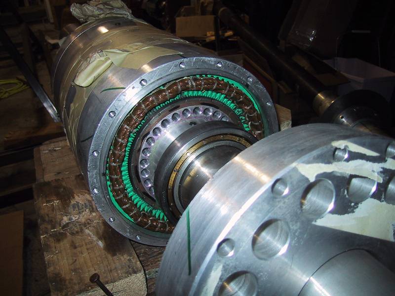
A look inside the generator housing - two separate 3-phase permanent magnet alternators utilize neodymium magnets.
Rotation is smooth at high wind speeds
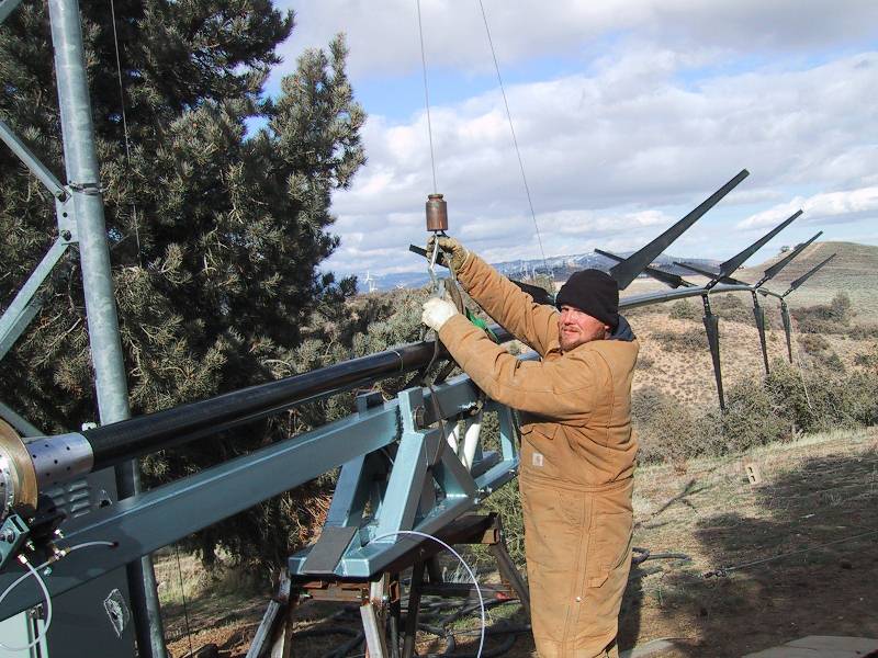
Brent Scheibel adjusts belts used for hoisting experimental turbine to the tower top.
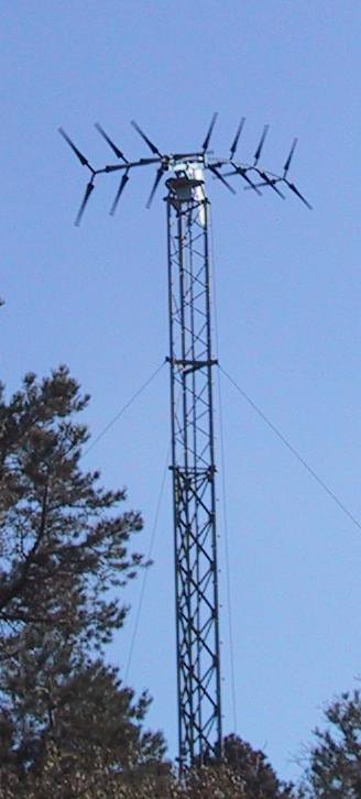
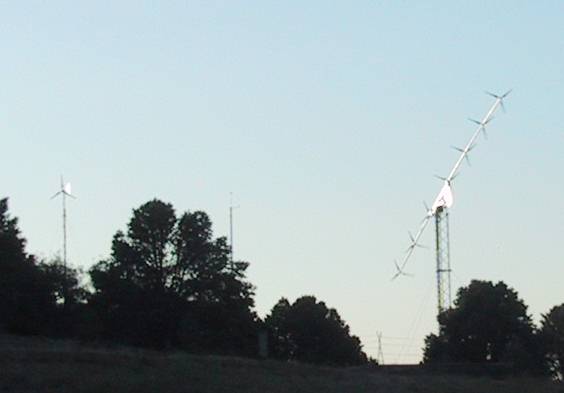
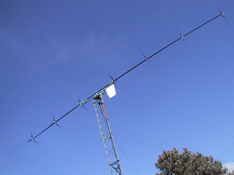
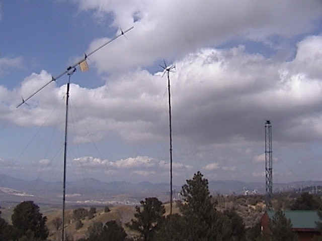
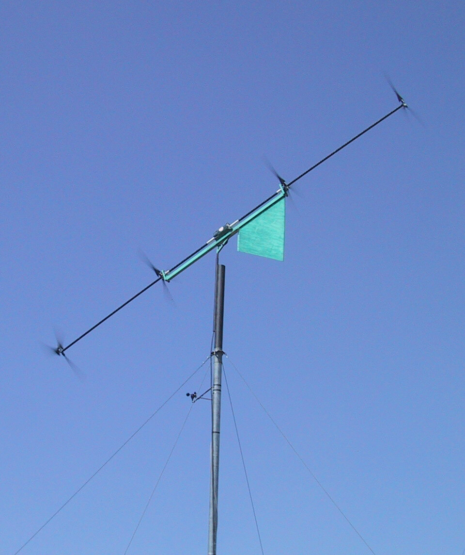
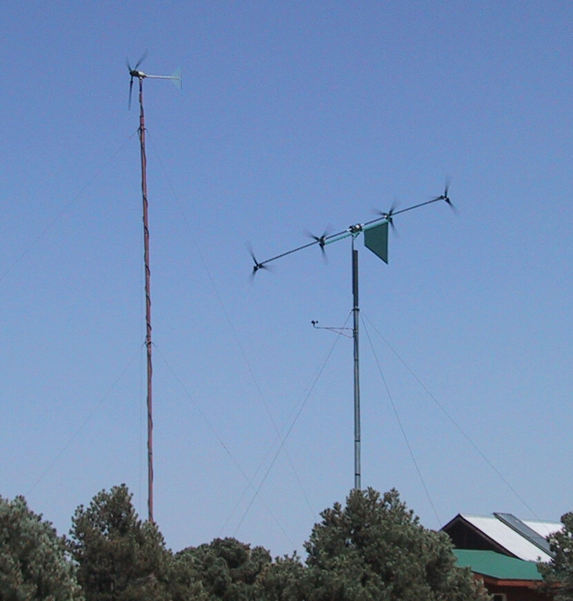
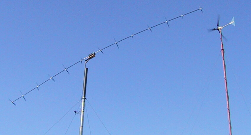
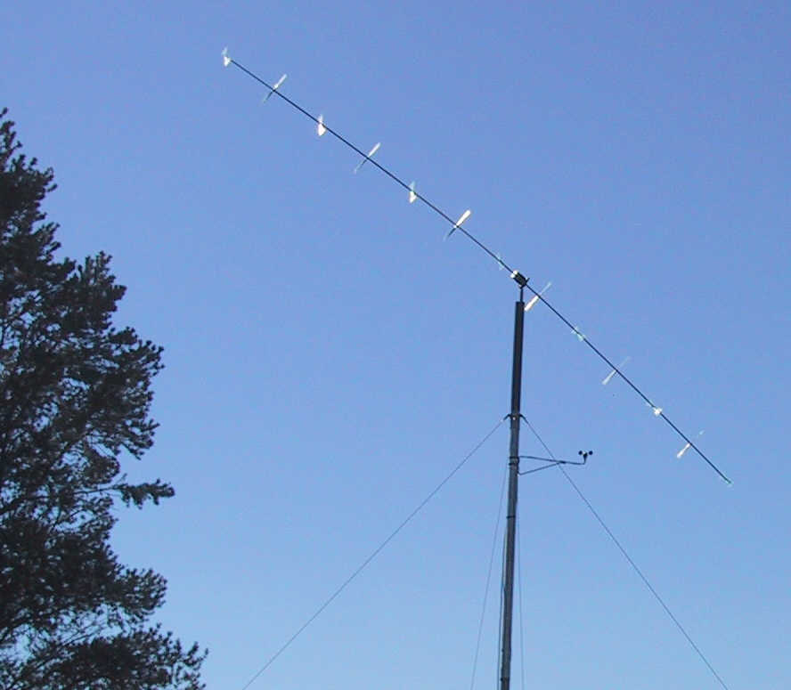
Selsam Multi-Rotor with anemometer and single-rotor turbine on separate towers
Lifting the turbine in the beautiful mountain environment of Tehachapi, CA at Windtesting.com
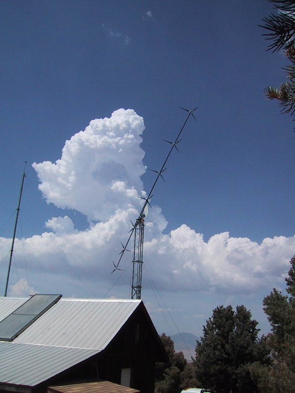
A light breeze in early summer 2004 at Windtesting.com in Tehachapi
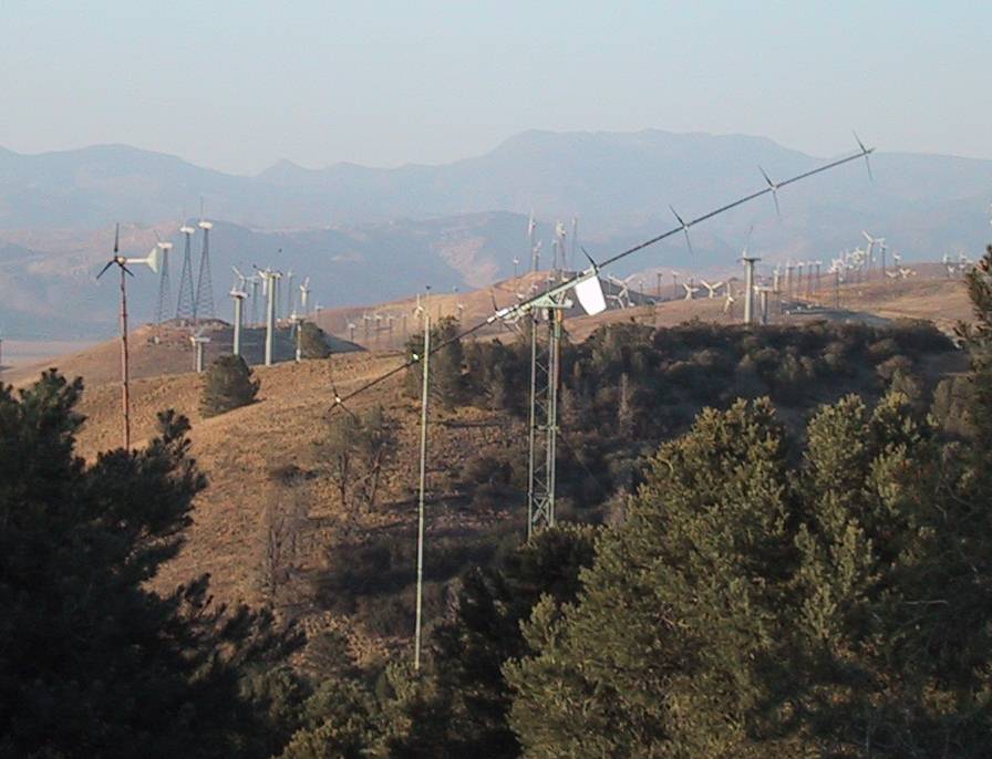
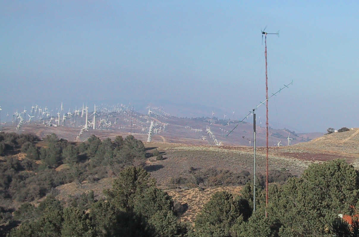
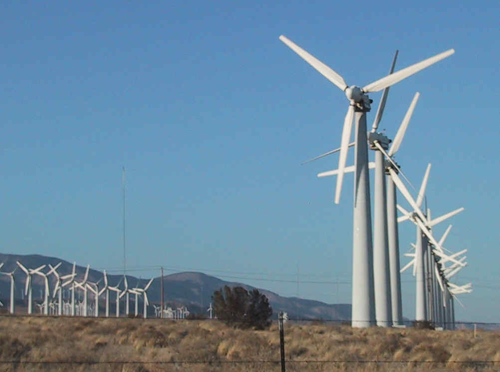
Co-axial, multi-rotor turbine set against a background of old-fashioned lollypop-style single-rotor turbines -
The multi-rotor gets 6 times the power for the same diameter.
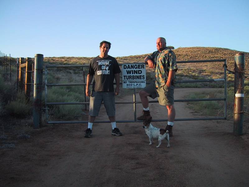
Doug, Brent, Ezra - Windtesting.com is a private, gated facility in the hills of Tehachapi, California
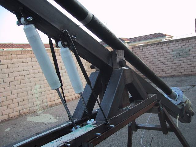
Gas shocks and gas springs regulate fore and aft tilt
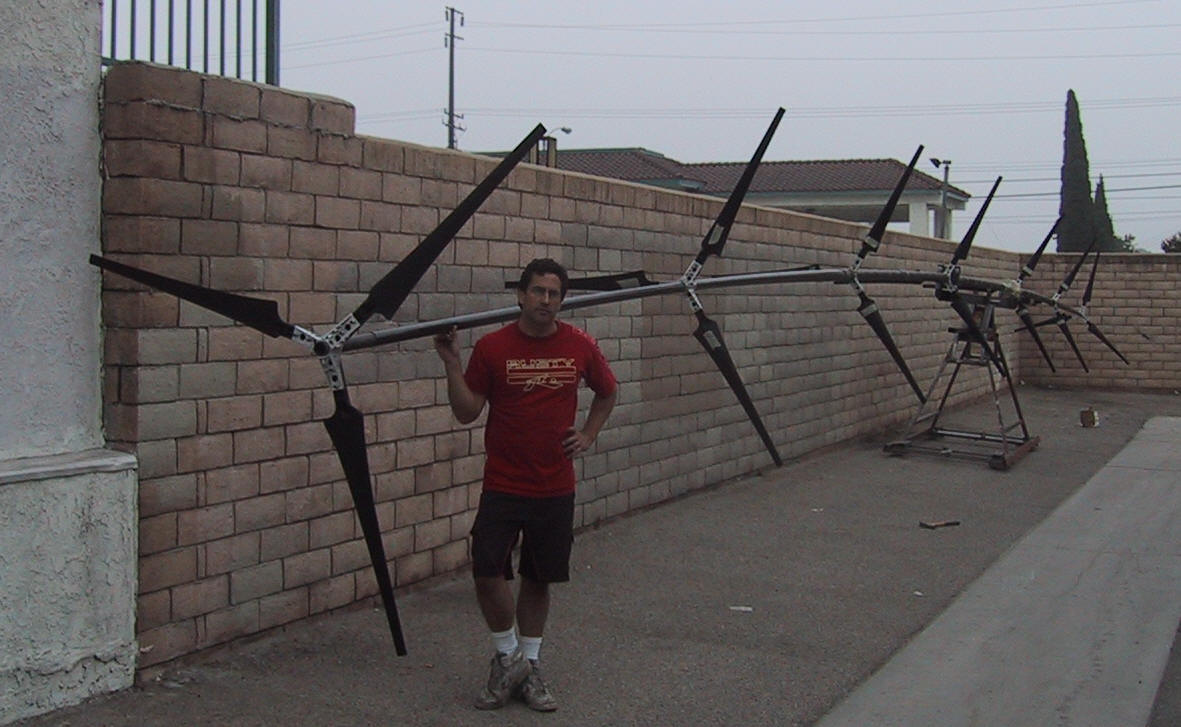
Doug Selsam with 3 kW prototype, utilizing seven 7-foot diameter rotors, nearing completion at ground level.
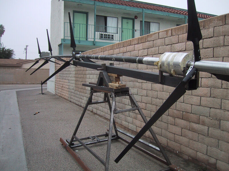
View from region of generator - 3 kW prototype Selsam Multi-rotor wind turbine partially assembled on stand at ground level
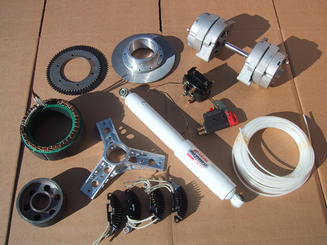
Parts is parts...hub, diodes, disk brake assembly, monoshock, alternators, and associated components used in our prototypes
Six rotors give many times the power of a single rotor turbine of the same diameter... an early six-rotor furling prototype from 2003
Experimental Prototype Selsam Wind Turbine with four 4-foot diameter rotors (left).
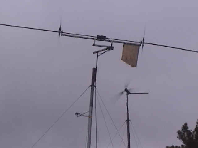
Selsam Turbine with four 4 foot diameter rotors furling to a horizontal configuration at about 30 mph, still producing full power. Downwind rotors are protected by the slipstream of the upwind rotor, limiting power production and thereby protecting from a runaway situation which would burn out the generator. This stops what would otherwise be a geometrically climbing power curve and
begins to level it out above the rated wind speed. Conventional "1000 watt" turbine can be seen furling sideways in background, cringing at the force of this strong wind, and consequently producing less electrical power when the wind speed is above the rated speed, where the best opportunity for producing instantaneous power actually exists.
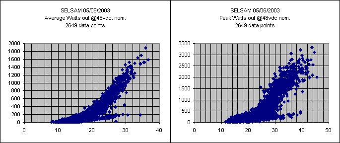
Power curves for a Selsam Multi-Rotor Wind Turbine with four 5 foot diameter rotors show a solid 1000 watts average power output at 28 - 29 mph. This is at 5000 feet elevation in Tehachapi, CA, where the air is about 14% thinner than at sea level. Most "1000 watt" turbines will actually average only about 600 watts at this windspeed, even if the data is corrected for altitude.
Notice that at 35 mph, where most small wind turbines are producing very little power due to sideways furling, we are producing 1600 average watts - 2000 average peak watts.
U.S. Patent Numbers 6,616,402 and 6,692,230 and other patents pending including international (PCT) http://www.uspto.gov
This "1 kilowatt" model produces 1200 watts at 33 mph
We see peaks of up to 1400 watts at 33 - 34 mph
New highest peak 1686 watts at ~34 - 35 mph!
We're calling this one the "Quadrunner" - We're pleased to see this prototype running very smoothly during the first few months of preliminary testing. Utilizing four 45" diameter sets of Air-X blades from Southwest Wind Power, placed approximately 7 feet apart, it's up and producing power during the first few weeks of operation. Preliminary readings show 800 watts at 27 mph, 1000 watts at 30 mph, and 1200 watts at 33 mph. We've seen peak output of 1400 watts at ~34 mph, and 1686 watts at wind speeds of ~35 mph. The generator is a dual-shaft 1 hp PM DC motor specially fabricated for us by Leeson Electric. In high winds, we are pushing this motor/generator over its designed power rating, as we had hoped we would, but it is well-cooled by the flow of wind, so it can handle the extra amps. The filament-wound carbon fiber driveshaft for the compound rotor is from Advanced Composites Products and Technology in Huntington Beach, CA. The frame is welded steel, as per the "heavy metal" design philosophy. Note that we are now utilizing a tail for quicker response to changes in wind direction. It is tracking perfectly. (Note: U.S. and International Patents issued and pending)
Here's the "Quadrunner" beside a Whisper H-40 from SWWP, which is a bit further from the camera, at the testing facilities of Windtesting.com. According to Brent Scheibel, founder and Chief of Operations at Windtesting.com, the two turbines are generating comparable amounts of power. The new "Quadrunner" has a much faster rotational speed (RPM), and so far makes a pleasant sound - not too loud either.
 |
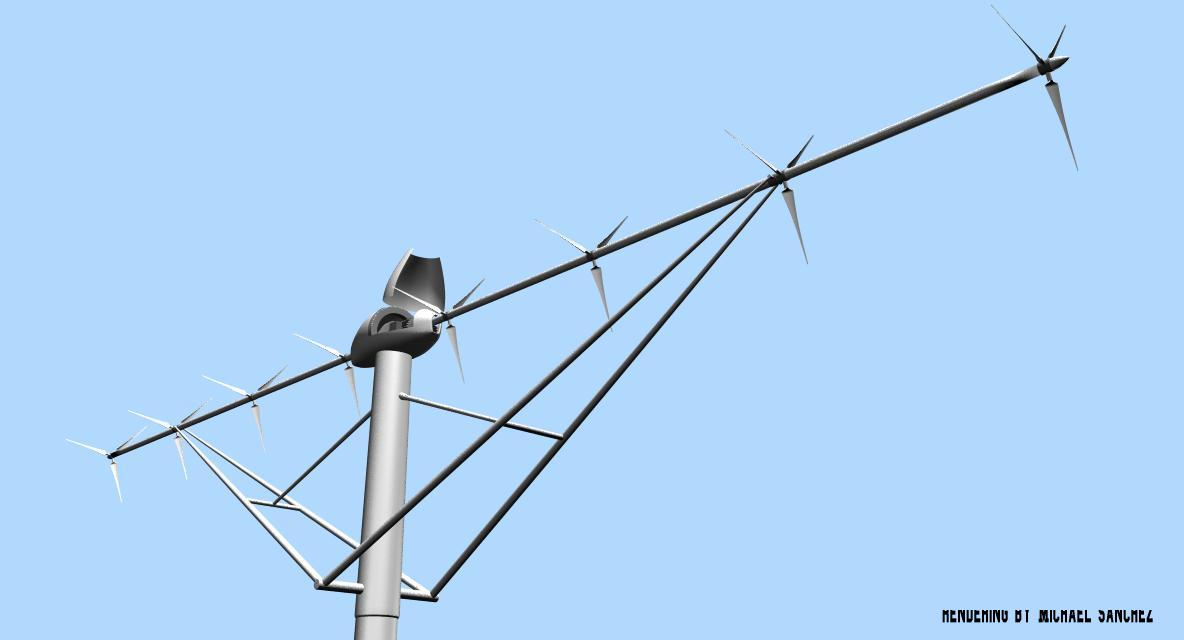
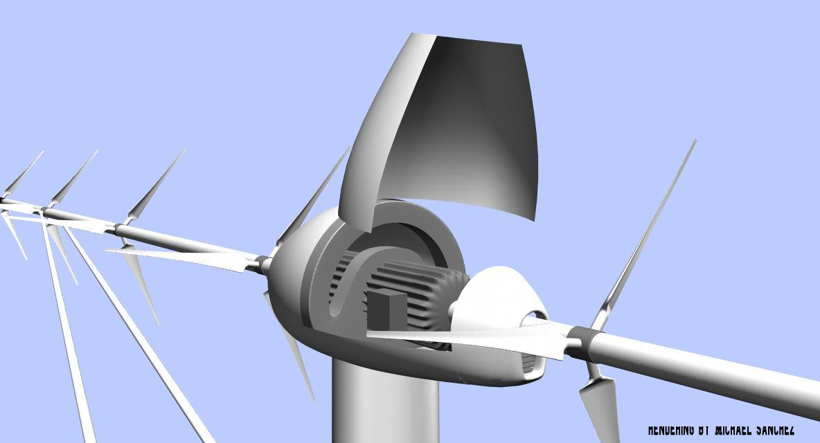
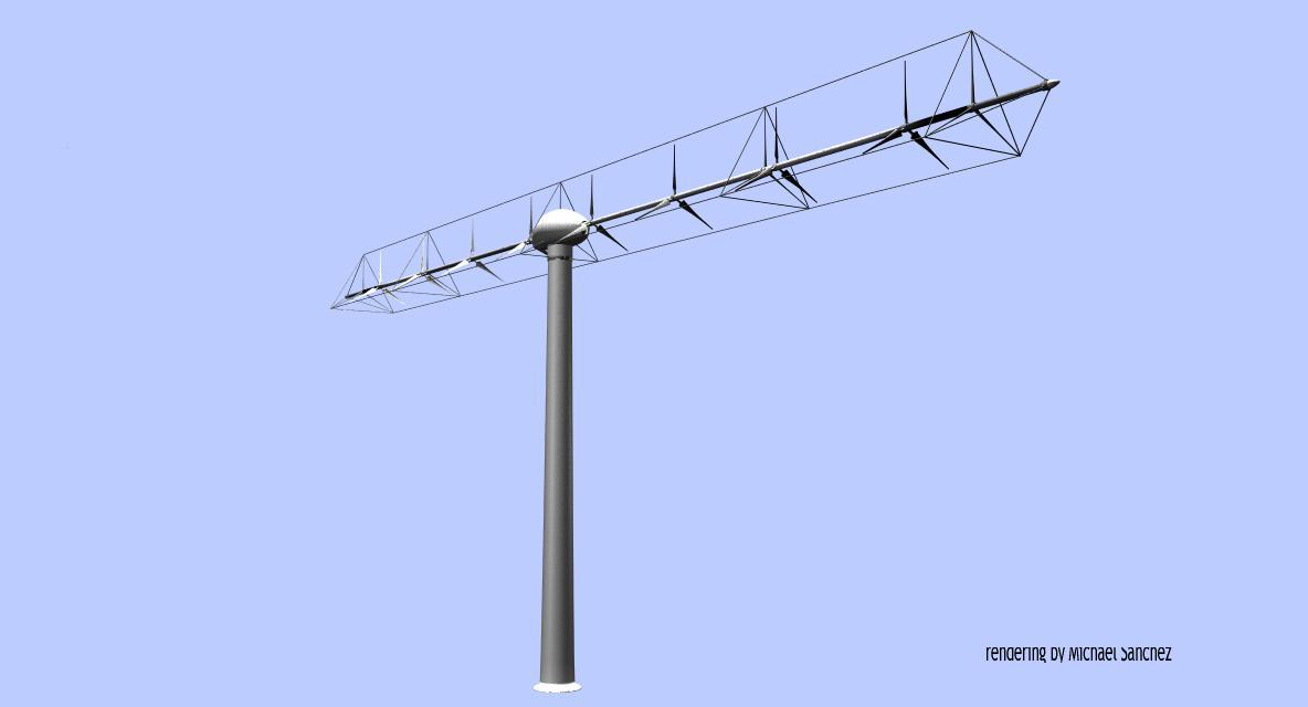
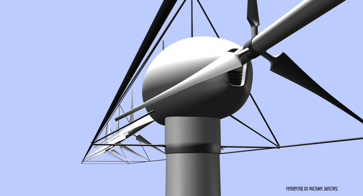
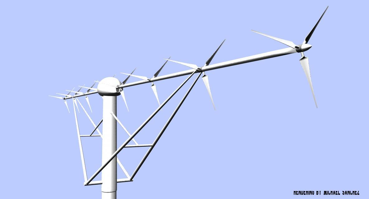
Above is a rendering of an 8-rotor model having an offset angle in the horizontal plane, Rendering by Michael Sanchez of Dreamworks, the movie animation company. To The left, a 3-rotor experimental Selsam Multi-Rotor Turbine unit is seen being tested at the facilities of Windtesting.com in Tehachapi, CA. It produces an average of 1200 watts at 30 mph at 5000 feet elevation. Below is an early prototype that was able to produce 400 watts using modified 18" diameter wooden model airplane propellers as rotors. |
U.S. Patent Numbers 6,616,402 and 6,692,230 and other patents pending including international (PCT) http://www.uspto.gov
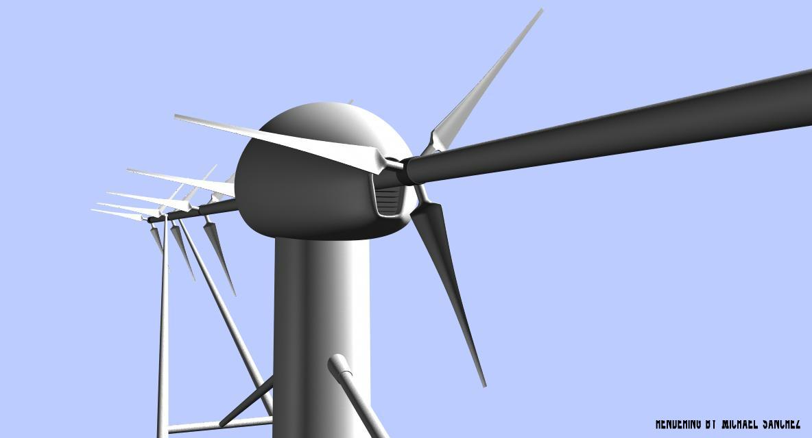
Rendering of a Selsam Multi-Rotor Wind Turbine by Michael Sanchez of Dreamworks Animation (above).
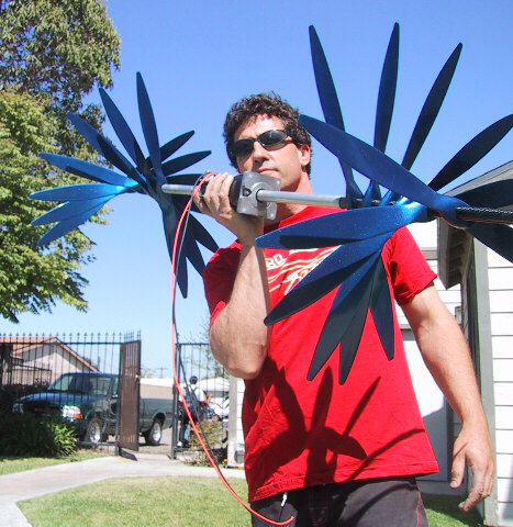 Ready to Rock - a "condensed" version shown for the photo, with a 3/4 hp generator, held by the inventor, Doug Selsam.
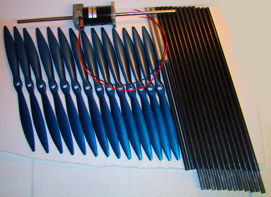
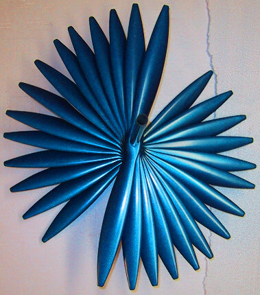
Here are the blades of a 20 inch diameter turbine, that produces about half a kilowatt. They will be mounted on a shaft that projects for a long distance forward, and backward, at an angle from horizontal, so that the wind encounters the rotors like a stairway. Each additional rotor brings more power. The combined output from all these small rotors really adds up.
This Turbine Utilizes Massive Parallel Wind Processing (MPWP) to maximize the wattage
generated for a turbine of a given diameter.
![]()
![]()
The New Turbine is flown in Tehachapi, mounted to a Tower by Brent Scheibel, of General Electric Wind and owner of WindTesting.com
Well, it's up and running, with data being logged. Not doing too badly on the first day. The winds are averaging in the teens, sometimes high teens, gusts in the low 20's. The faster it turns, the smoother it runs. With 18" diameter rotors, we're putting out a varying current running between 100 and 200 watts. At 30 mph we get about 400
watts.
![]()
![]()
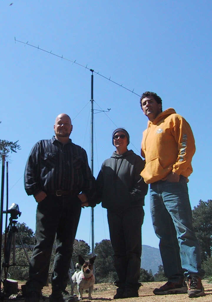
Brent Scheibel, WindTesting.com, His wife, Teri, with their dog Ezra, and Doug Selsam, windmill is seen in background
This is the test team, Brent Scheibel, who handles Anemometry over at Zond / Enron Wind - now General Electric Wind Energy, and runs Windtesting.com, His wife Teri, their dog Ezra, who barks at windmills, and Doug Selsam, the inventor. Brent really knows his windmills, from the biggest to the smallest, and handles large towers with ease.
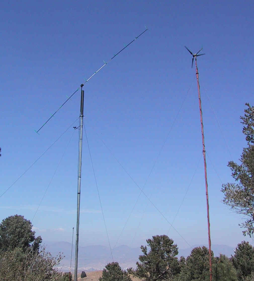
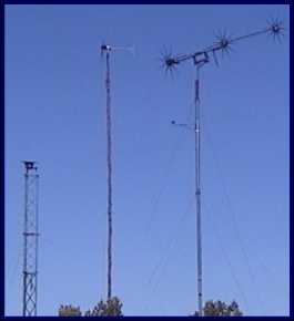
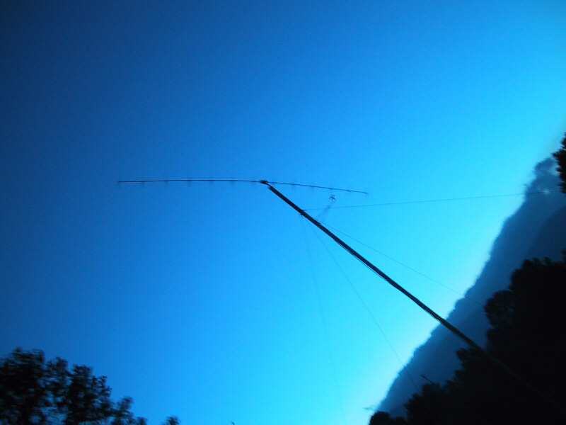
The Sky Serpent, flying alongside Brent Scheibel of Windtesting.com's SWWP 900 watt turbine. Enron (now G.E.) Wind Farm barely visible in background
![]()
![]()
![]()
![]()
Row after row of clean-turning turbine blades adorn the landscape... pretty cool.
U.S. Patent Numbers 6,616,402 and 6,692,230 and other patents pending including international (PCT) http://www.uspto.gov
![]()
![]()
The Mitsubishi Heavy Industries Wind Farm, down the road. Row upon row of rotors, each with its own separate tower and generator.
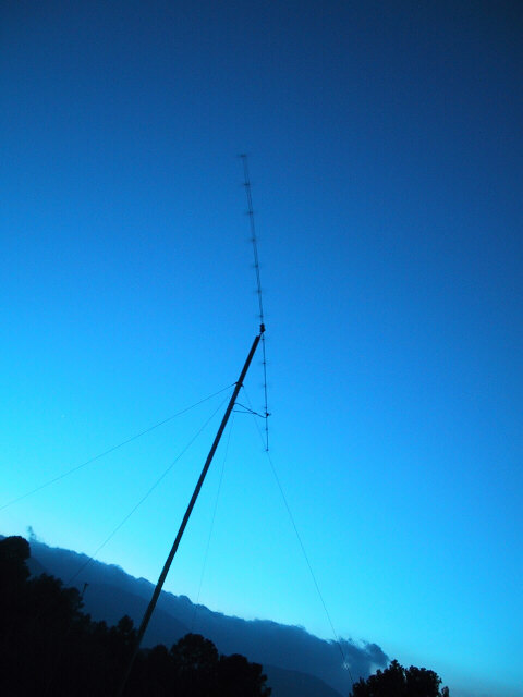
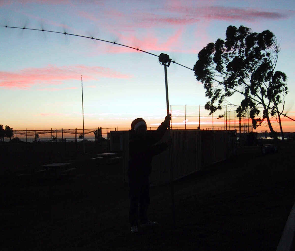
As evening falls, the sky serpent flies on...
and on into the night, what adventures await...
U.S. Patent Numbers 6,616,402 and 6,692,230 and other patents pending including international (PCT) http://www.uspto.gov
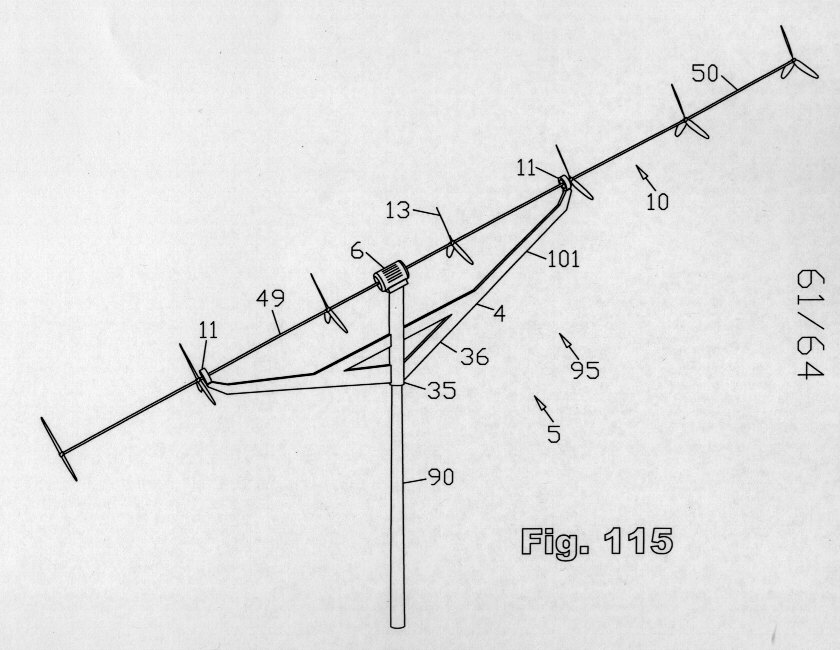
Balanced, High-Output, Rapid-Rotation Wind Turbine
U.S. and International Patents Pending
Douglas Spriggs Selsam
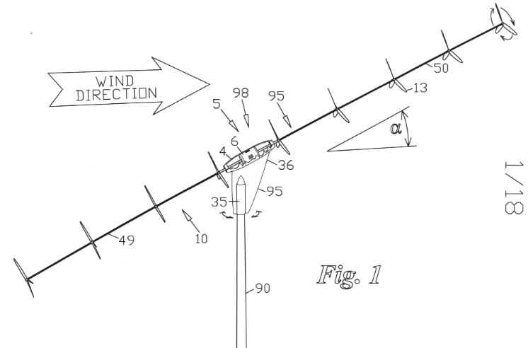
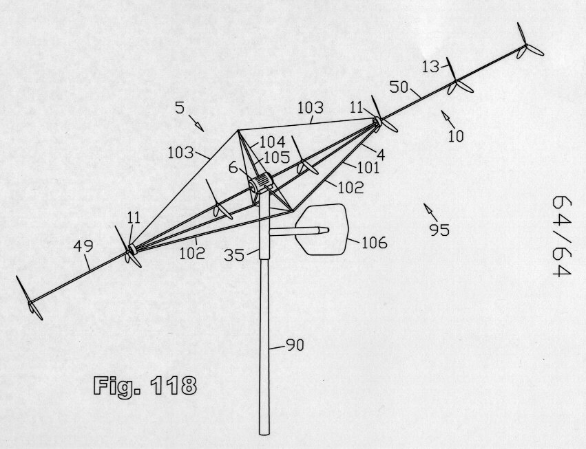
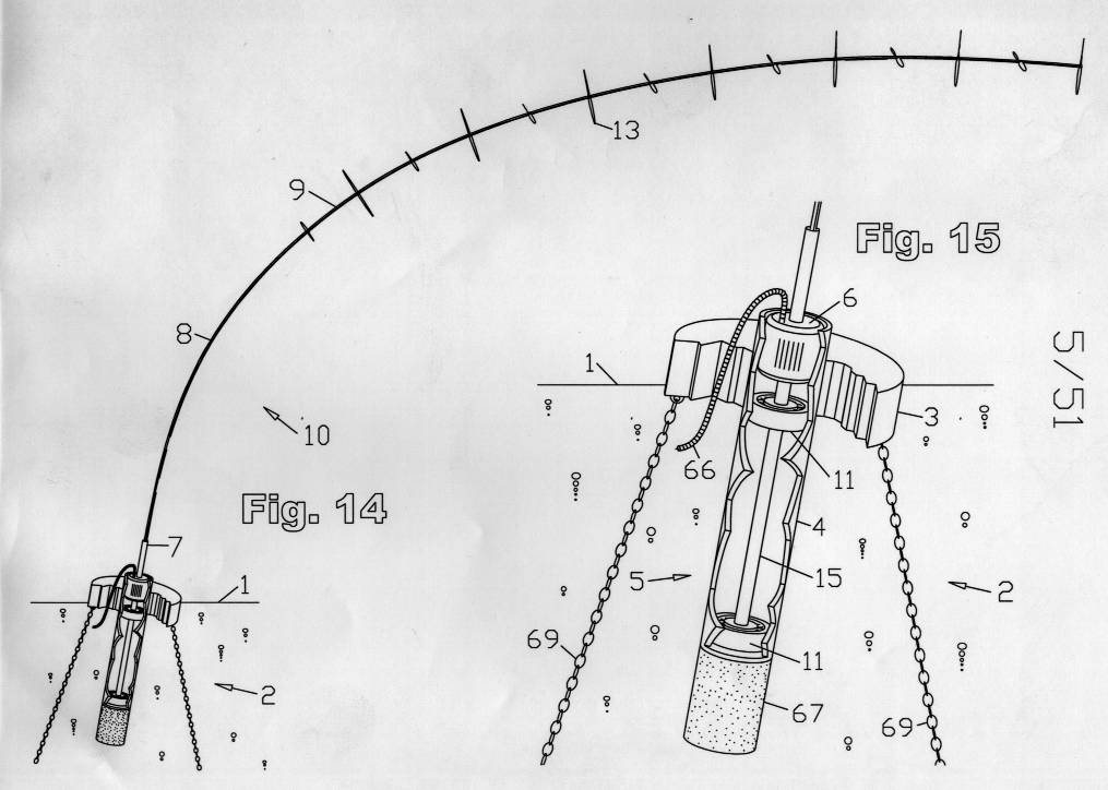
An illustration from pending U.S. Patent 6,692,230:
"Balanced, High Output, Rapid Rotation Wind Turbine"
![]()
![]()
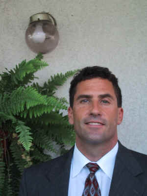 Doug Selsam
![]()
![]()
Currently Used Technology:
Current wind turbines are a refined version of a 1000 year old design, originated when cast iron was a high tech material. These wind turbines suffer from the following problems, challenges, and drawbacks:
![]()
![]()
![]() Our Multi-Rotor technology neatly solves all of these classic problems in wind turbine design. Our new design, now proven in small models, combines the power of multiple smaller rotors mounted to a single elongate driveshaft, to give the same power as a single larger rotor,
with less cost, weight, and complexity. Smaller rotors weigh less for the swept area, and turn faster, thereby dispensing of the need for a gearbox. Our new design is naturally self-aiming, requiring no dedicated apparatus to achieve this, and is generally simpler, having fewer moving parts, requiring less maintenance. We expect to validate this revolutionary
California design, using multiple rotors coupled to a single elongate shaft as being able to harvest more wind energy at less cost than current models which use only a single rotor.
Our Multi-Rotor technology neatly solves all of these classic problems in wind turbine design. Our new design, now proven in small models, combines the power of multiple smaller rotors mounted to a single elongate driveshaft, to give the same power as a single larger rotor,
with less cost, weight, and complexity. Smaller rotors weigh less for the swept area, and turn faster, thereby dispensing of the need for a gearbox. Our new design is naturally self-aiming, requiring no dedicated apparatus to achieve this, and is generally simpler, having fewer moving parts, requiring less maintenance. We expect to validate this revolutionary
California design, using multiple rotors coupled to a single elongate shaft as being able to harvest more wind energy at less cost than current models which use only a single rotor.
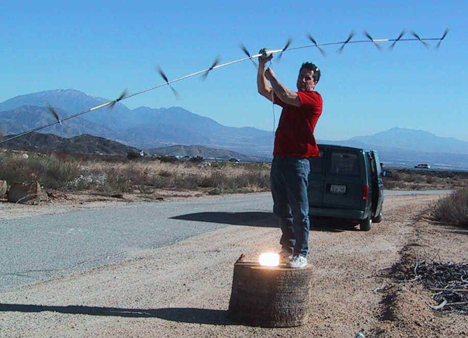
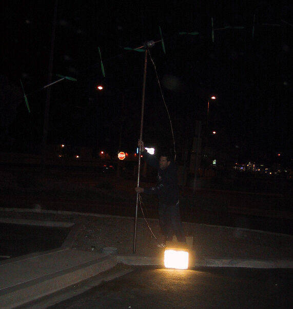
The car headlight at Doug's feet is 50 watts The rotor size is only fourteen inches! Wind speed in the 20's mph (more rotors produce more power)
![]()
![]()
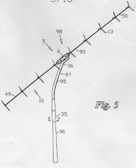
![]() Our new proprietary California design utilizes a multiplicity of rotors mounted at spaced intervals along a single elongate driveshaft. This lightweight yet strong carbon fiber shaft is aimed into the wind, with the nose pointing slightly downward, so that each rotor encounters fresh, undisturbed wind.
The shaft is balanced fore and aft about a centrally located generator, which it directly drives. This assembly is mounted so that the center of aerodynamic drag is slightly downwind of an azimuthal pivot point, making it conveniently self-aiming while using no extraneous device to achieve this self-aiming behavior.
Our new proprietary California design utilizes a multiplicity of rotors mounted at spaced intervals along a single elongate driveshaft. This lightweight yet strong carbon fiber shaft is aimed into the wind, with the nose pointing slightly downward, so that each rotor encounters fresh, undisturbed wind.
The shaft is balanced fore and aft about a centrally located generator, which it directly drives. This assembly is mounted so that the center of aerodynamic drag is slightly downwind of an azimuthal pivot point, making it conveniently self-aiming while using no extraneous device to achieve this self-aiming behavior.
The result is a lighter, faster-turning, self-aiming, simpler, more reliable wind turbine, having fewer moving parts, using substantially off the shelf components.
The inventor, Doug Selsam, testing a small prototype of an entirely new class of wind turbines
What Makes Our New California Class of Wind Turbine Better?
A Detailed Explanation of the Advantages:First, let�s look at some of the problems with wind turbines today � then see how our design solves these problems.
Existing Wind Turbines, using the modern "Danish Design", based on the "Old Dutch" design, have made great advances, and are indeed awesome machines, yet suffer from certain classical challenges. We will address our solutions to these problems one at a time:
The volume, and hence the mass, of a rotor is proportional to the diameter cubed, while the swept area is only proportional to the diameter squared. (typical volume/area relationship for any solid, 3-D object) This means that the amount of wind a rotor can capture, in relation to its mass, is inversely proportional to rotor diameter. In other words, if a rotor�s diameter is increased by 10 times, the area (and hence the amount of wind captured) is increased by 100 times (good), however, the mass has increased by 1000 times! (bad) The larger turbine can only capture a tenth as much energy compared to its mass! This simple mathematical fact tends to limit the size of current single-rotor wind turbines. (Note that this same effect of scale is the reason why an ostrich can�t fly, while a small flock of geese, weighing the same amount in total, can easily undergo transcontinental migrations, and a hummingbird, whose name we borrow for our smallest model, can easily hover.) The largest turbines have rotor diameters of well over 100 feet. These monstrous structures must be made to perform for many years, and have many problems with stress and fatigue. The giant blades are notoriously difficult to manufacture and ship.
Currently used Solution: Keep making larger and larger single-rotor turbines anyway, regardless of the inherent problems of scale, because nobody has thought of a better solution.
OUR SOLUTION: Smaller Rotors weigh less per unit of swept area.
We mount multiple, smaller rotors, at spaced intervals along a very elongate, carbon fiber composite driveshaft. (The shaft is at a slight angle from the wind direction so each rotor gets its own fresh wind.) Multiple small rotors weigh much less than a single larger rotor sweeping an equivalent total area, can be much lighter in construction, and are far easier to produce.
They consume less material, cost less, and are much less subject to material fatigue.
![]()
![]()
For a given wind speed, the rate of rotation (RPM) of a rotor is inversely proportional to rotor diameter, meaning that larger rotors turn more slowly. The largest turbines rotate at less than one revolution per second. Generators, on the other hand, require a faster rate of rotation (typically 1800 - 3600 rpm). There are two classic solutions to this problem, both of which add cost, weight, and complexity to a wind turbine:
Currently used Solution #1 to remedy slow rotation � Add a gearbox: A gearbox can be used to convert the slow rotation provided by a large rotor to the faster rotation required by a generator. This solution is heavy, expensive, noisy and introduces a source of friction, wear, and unreliability to a wind turbine. Reliability is of paramount importance in a wind energy installation. Gearboxes consume about 20% of the cost of current wind turbines.
Currently used Solution #2 to remedy slow rotation � Use a specially-built, low speed generator or alternator, having many more poles than usual: Small to medium-sized wind turbines often feature specially-built alternators having many extra poles, to generate useful power at a slower rate of rotation. This strategy allows the alternator to be directly driven by the rotor, saving the wear, expense, and power loss introduced by a gearbox. Unfortunately, this strategy has its own drawbacks, being:
OUR SOLUTION: Small rotors rotate faster than larger ones, so for small to midsize turbines of our new design, a conventional generator or alternator can be directly driven within a proper rpm range. Multiple rotors give more power for the same diameter than a single rotor. Our design needs no gearbox. (Very large turbines of our new design may utilize some gearing, but, due to
faster rotation, it need be much less robust for the power generated than current models require.)
![]()
![]()
The robustness required of a driveshaft transmitting a given amount of power is inversely proportional to rpm. A typical wind turbine drivetrain has a very heavy shaft to support the single, ponderous, slowly-turning rotor, and to transmit its power to the gearbox. The slowly turning portion of the gearbox must be similarly robust. Not only is it transmitting a large amount of power at an excruciatingly slow rate of rotation, but this low speed driveshaft and its bearings are supporting the huge rotor in a non-balanced, projecting, cantilevered manner.
As the rotational speed increases within the gearbox of a conventional wind turbine, the gears and driveshafts become less robust. The output shaft of the gearbox - the quicker-turning shaft that actually drives the generator - is much thinner and less massive than the input shaft driven by the single giant rotor.
Currently used solution: Designers have no choice but to make the rotor end of the drivetrain much more robust than the generating end.
OUR SOLUTION: A Faster-Turning Driveshaft can be less robust for the same power: Our higher speed drivetrain need not be more robust than what is required to drive the generator, and to support the multiple, lightweight rotors.
Also, Our New Design is Better Balanced: Our Generator is located approximately at the center of our driveshaft. Our elongate carbon fiber composite driveshaft with its multiple small rotors, weighing much less than a single large rotor sweeping an equivalent area, is supported near its midpoint by the bearings of the generator, and so is also approximately balanced about these bearings, fore
and aft, rather than being cantilevered in one direction, and needs no other bearings.
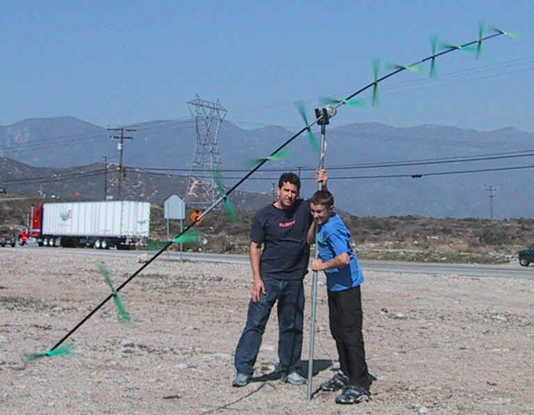
 |
An easy 200 watts in about a 20 mph wind or so, lighting the four 50 watt car headlight bulbs you see at Doug�s feet. We get much more power than this in higher winds. This kind of power output is unheard of for an 18" diameter horizontal axis windmill! � the secret? Multi-Rotor technology, made possible by the strength of modern carbon fiber materials. This rotor is really thirteen rotors harnessed as one, giving an order of magnitude (~10 times) more power than a single rotor design of the same diameter. In stronger winds this prototype blows out these lights like flashbulbs - poof! |
![]()
![]()
4. Problem #4 - Special, dedicated apparatus required for directional aim, adding mass and complexity: Current wind turbines are not self-aiming.
Currently used Solutions:
Either of these currently used solutions to the aiming problem adds mass, complexity, and cost to the installation.
OUR SOLUTION: Self-Aiming Behavior: Our machine simply locates the center of aerodynamic drag downwind of an azimuthal pivot point. This may be accomplished by either having the driveshaft slightly offset to the aft direction, or by having the entire assembly offset slightly downwind from a master pivot point. 6 rotors upwind and 7 rotors downwind has been working well so far. The machine eagerly seeks
the wind, and stays headed windward.
![]()
![]()
5. Problem #5 � Inordinately complex mechanisms required to prevent damage in gale force winds � any wind turbine that is efficient at gathering wind will be in danger of damage should that wind reach excessive velocities. Some means must be provided to prevent such damage.
Currently used Solution: Current wind turbines require either a special mechanism to "furl" the single rotor (turn its aim sideways to the wind) or a means to adjust the pitch of the blades, to prevent damage in storms. This adds further to the cost and complexity of the installation.
 |
OUR SOLUTION: Simple protection from damage in excessively high winds - Our new design is resiliently mounted at a slight angle from horizontal. In high winds, the resilient carbon fiber composite driveshaft is pushed to a more horizontal position, placing the rotors directly in line with the wind and with each other, so that upwind rotors act to shield downwind rotors (wind shadow effect). This protects from overspeed conditions. |
![]()
![]()
6. Problem # 6 Excessively Robust Support Structure Required: All of this inordinately heavy equipment, including the disproportionately massive blades, must be installed and supported at a sufficient height to encounter strong winds. The heavier this equipment is, the more robust must be the support structure. The single super-massive rotor carries a huge amount
of angular momentum, and so is not very tolerant of flexibility in the tower, instead requiring a "hard mount".
Currently used Solution: use more steel in the tower to make it stronger. Today�s towers account for about 20% of the cost of a turbine installation.
 |
OUR SOLUTION: Less robust supporting structure required: - Lighter weight and less angular momentum, as well as the balanced mounting, and the resilience of the elongate driveshaft of our new design, allow a lighter tower to be used, even one that has some "give". |
7. Problem #7 - Maintenance: Complex machinery requires more attention and maintenance for continuous operation. Such maintenance is made more complicated by the fact that the equipment is at a dangerous height above the ground, and often, by its very nature, in a remote location.
Currently used Solution: Hire more personnel, and buy more equipment, vehicles, tools, lubricants and replacement parts, to constantly attend to the complex mechanisms.
OUR SOLUTION: Less Maintenance required - Fewer moving parts and a simpler method of operation translate to less labor, equipment, vehicles, tools, and spare parts required to keep it all running smoothly.
![]() This vast improvement over the state of the art utilizes the lightweight strength offered by recent advances in composite materials to place multiple rotors along a single shaft. Multiple small rotors are lighter, and rotate more rapidly compared to a single rotor of equivalent area. More rapid rotation reduces or eliminates the need
for a gearbox. Extreme reliability demands such simplicity. This entirely new class of wind turbines is balanced, and self-aiming, with an offset from horizontal to allow each rotor to encounter fresh wind.
This vast improvement over the state of the art utilizes the lightweight strength offered by recent advances in composite materials to place multiple rotors along a single shaft. Multiple small rotors are lighter, and rotate more rapidly compared to a single rotor of equivalent area. More rapid rotation reduces or eliminates the need
for a gearbox. Extreme reliability demands such simplicity. This entirely new class of wind turbines is balanced, and self-aiming, with an offset from horizontal to allow each rotor to encounter fresh wind.
Because our rotors cost less, having far less total mass, and our generator costs less, and the gearbox is eliminated, and our drivetrain, rotating at a faster rate, can be less substantial and still deliver the same power, and because it is self-aiming, requiring no azimuthal guidance system, our new windmill can be made for less than half the price of the competition. Because it is lighter and better balanced, with less angular momentum, and a resilient driveshaft, a lighter guage tower can be used. For these same reasons it�s safer. And because it's simpler, it requires less maintenance, and has less downtime than current designs.
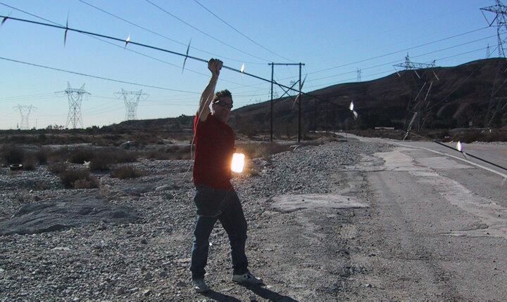
14 inch rotors lighting a 50 watt car headlight. More rotors = more power! So balanced it's comfortable to hold right in your hand - and very easy on the bearings!
Doug's First Windmill Invention:
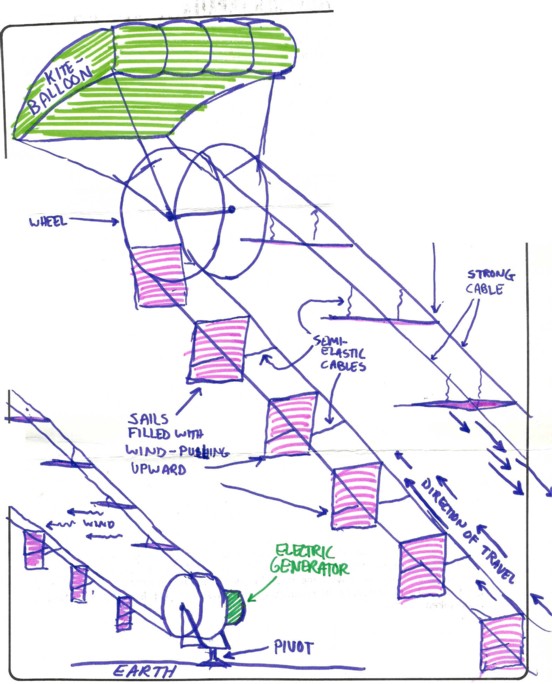
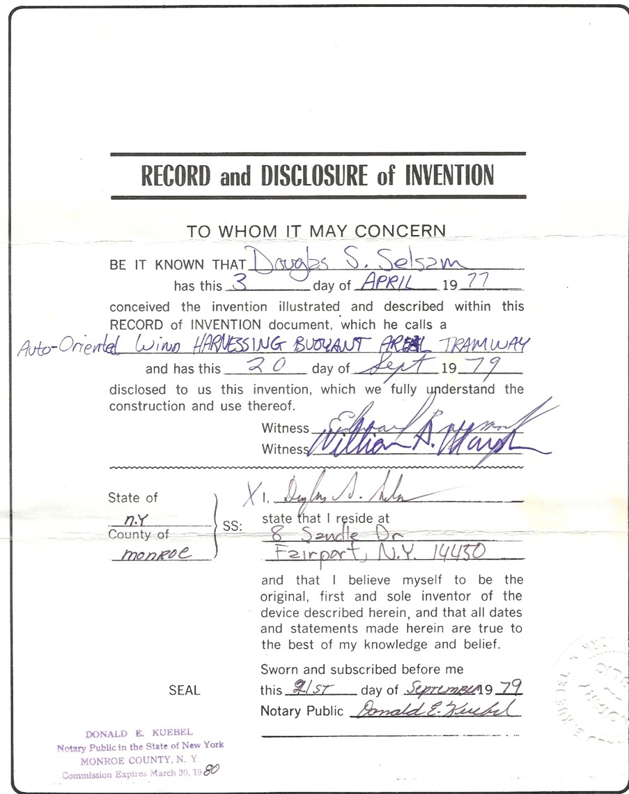
Doug Selsam has been designing the most advanced wind turbines in the world since 1979! See, documented below, "Auto-Oriented Wind Harnessing Buoyant Aerial Tramway" what has recently been called a "Laddermill" http://www.laddermill.com/, http://www.ockels.nl/ and which has been a granted a U.S. Patent 6072245 in 2000.
Below is witnessed, notarized documentation, pulled from a safe deposit box for 21st century scanning, with both color drawing and written description, that Doug invented his "Wind Harnessing Buoyant Aerial Tramway" in 1977 at age 19. See comments below:
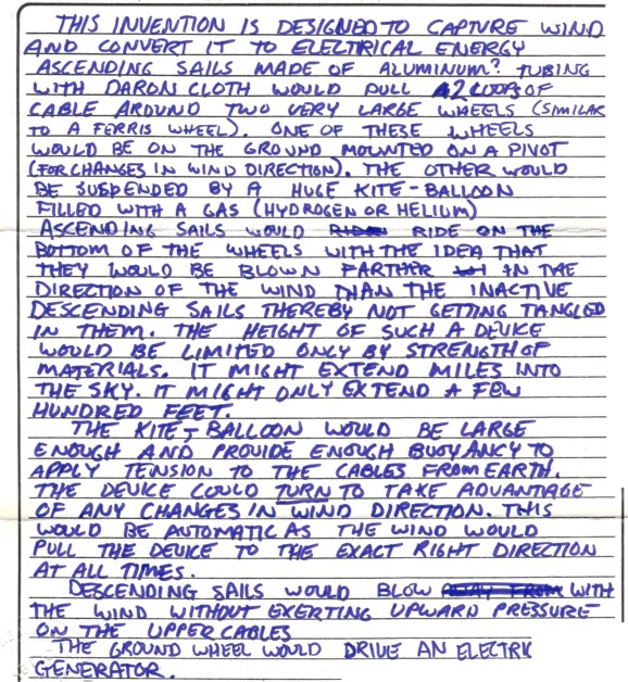
Back in the 1970's people were a bit puzzled at Doug's ideas for advanced wind turbines, and skeptical of his claims that wind was "the future of energy". Back then most people didn't know much about a lot of things that we take for granted today. Doug never pursued "Auto-Oriented Wind Harnessing Buoyant Aerial Tramway" design, because of:
1. The blades have a relatively low aspect ratio, with high tip losses;
2. If the blades are made relatively wider to avoid tip losses, then the downwind blades travel through the wake of upwind blades;
3. It is somewhat of a drag-based machine, at least on the downwind journey;
4. Many unknowns to address regarding storms and quickly-changing wind direction with possibility of entanglement;
5. Similar configurations that rotate, instead of traveling downwind then upwind, were in fact the basis of the inventor's patents on multi-rotor wind turbines. Doug moved on to the multi-rotor, horizontal-axis design because, similarly to single-rotor turbines and to earthbound turbines, even in the 1970's, horizontal-axis type rotors were known to be the best use of material, yielding the highest rpm and most
power for the material used. And that is the idea, more power generated for less material used.
Products and Projects Planned:
We plan to continue building larger and larger prototypes of our California design, developing at least one for commercial production. We will also continue to develop related designs, and continue to secure intellectual property protection for the entire family of designs.
Unique Capabilities:
Our patent pending California design is lighter, faster, simpler, quieter, and self-aiming, more reliable, with fewer moving parts, delivering more energy for the money.
Competition:
Virtually all other companies in the wind energy business are now using the "Danish Design" based on the ancient "Standard Dutch" single rotor design at this time. We predict that, rather than being competition, other wind energy companies will become partners and/or licensees utilizing our superior technology.
Market Penetration Strategy:
We plan to continue development of our new class of wind turbines, to prove that the technology will work in a small to medium sized installation, and to produce at least one production model for commercial sale. We project that the resulting test data, as well as the attention garnered from the superior performance of our production models, based on cost per kilowatt hour, will create a demand for licensing by others. We will also continue to develop some of the more advanced versions of the California design, incorporating a rotating tower/driveshaft and/or atmospherically buoyant versions. These even more advanced technologies may become production models or licensed to others.
Strategy and Objectives:
The immediate objective is to prove the technology for a new and improved class of wind turbines, by building and testing a reliable prototype of a size suitable for household use. This entirely new class of wind turbine is expected to further reduce the cost of wind power. We expect to eventually to derive a revenue stream from our overall, long term effort. The more far-reaching objective is to reduce dependence on oil and other fossil fuels, from whatever source, making the world a cleaner and safer place.
The overall strategy is:
Accomplishments:
Currently funded by The California Energy Commission
http://www.energy.ca.gov/contracts/smallgrant/2003-02-21_awards_02-02.html
U.S. Patent Numbers 6,616,402 and 6,692,230 and other patents pending including international (PCT) http://www.uspto.gov
Q1. Doesn't the wind shadow from one rotor inhibit the next rotor from getting wind?
A: That's definitely a factor to consider. Our driveshaft is at an angle from horizontal, with the nose pointing slightly downward so that, with proper spacing, each rotor gets its own wind. In addition, the forward tilt of the rotors tends to direct the wind downward, pulling more fresh wind through the machine from above...
Any slight losses of power from wind shadow effects are more than made up for by the overwhelming combined power of a multiplicity of rotors.
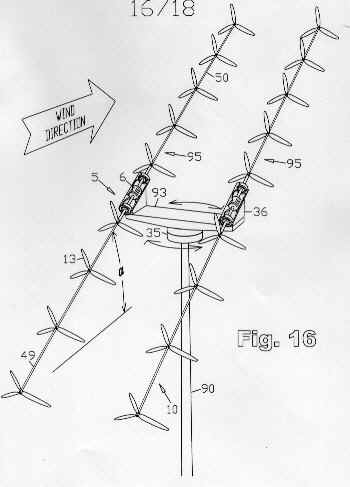 |
Q2. Can two or more of the Selsam Multi-Rotor Wind Turbines be combined on a rotating frame to form a single self-aiming wind-power-production structure? A: Yes. Multiple turbines mounted to a single rotating armature are self-aiming as a combined unit. Multiple levels are also possible. Q3. Is the Selsam Multi-rotor wind turbine well suited for rooftop mounting? A: Yes! The low profile design makes good use of the flow of air over a roof. The multiple rotors combine for smooth, quiet, relatively vibration- free operation. |
Q4. What about the fact that the horizontal axis rotors aren't aimed exactly into the wind, but instead are aimed slightly downward from horizontal? Don't they lose a lot of power?
A: Another good point. Luckily, a slight deviation from the wind direction has almost no effect on a rotor's performance. The offset angle can also be in another plane, such as horizontal, useful in larger installations where rotor size is a significant fraction of tower height.
Q5. What about the bearings? Isn't there a lot of radial loading from the weight and wind loading amplified by the leverage of the length of the shaft?
A: The upwind section of the shaft approximately balances the downwind section. This minimizes radial loading on the bearings. That allows long bearing life.
Offshore versions require no rigid foundation, no heavy steel tower, run at high rpm to directly drive a generator that is easily accessible from surface level. Multiple small rotors sweep the same area with less blade mass. These floating offshore units may be towed into position, no crane required, simply tilt over to service.
Q6: Why doesn't it need a tail, or a dedicated azimuthal orientation means of any kind?
A: We feel that since a tail doesn't contribute any power, get rid of it and put on something that does produce power, like more rotors. A conventional tail is like a partner on a tandem bike who refuses to pedal! We simply place the center of aerodynamic drag of the entire driveshaft with its attached rotors slightly downwind of an azimuthal pivot point, and the machine will faithfully stay headed windward. OK sometimes we use a tail too, it depends...
Q7: What about protection in high winds?
A: Several factors act to protect the machine in high winds: First, at the higher reynolds numbers that come with increasing wind speeds, the length of wind shadows effectively increases, so that upwind rotors will begin to protect downwind rotors. More importantly, the downwind section of the shaft will tend to bend to a more horizontal direction, placing downwind rotors more into the wind shadows of the upwind ones. Finally, the generator and shaft can be resiliently mounted, so that they are blown into a more horizontal orientation by very strong winds, so that overall rotor exposure is reduced, while power output and rpm are maintained. They key to proper behavior at all wind speeds is that progressively more rotor surface is exposed in low winds, and less in high winds. No furling cycle is involved, so there is never a time when no power is generated because of excessively strong winds. The action is also not as radical as furling, and is less prone to "finicky" behavior.
Q8: Now that you've shown how to get 5 times the power for a given diameter turbine on land, have you solved all of the major challenges in offshore as well?
A: Well yes as a matter of fact we have. Our offshore version can be deployed as a floating installation in water of any depth, making windfarms off the coast of California feasible. It looks like a giant fishing pole supporting rotors at spaced intervals. It tilts with the wind, and bends downwind as well. It conveniently dispenses with the rigid foundation, the gearbox,
the yaw bearing, the yaw mechanism, the heavy steel tower, directly driving a generator at relatively high rpm. The generator is at or near surface level. The entire turbine comprises only a single moving part, no slip rings or brushes No crane is needed for deployment or maintenance. These floating turbines can be towed into place. They flex with the action of waves while spinning.
Q9: What other designs do you have in mind for the future? Are they also covered by your patents pending?
A: Yes, and the future is wide open. This design is an important advance, yet is still just the tip of the iceberg. Future patent pending designs include atmospherically buoyant versions that incorporate helium-filled or hydrogen-filled kite-like aerodynamic lifting bodies instead of a tower. Others utilize buoyant, inflated rotors. We have much more advanced designs still. We have
had preliminary discussions with some NASA personnel indicating that such turbines might find use as easily deployable power sources on Mars.
Q10: Despite all the logical reasons why this new design seems to be a step forward, I'm having trouble accepting it. It seems too simple or something - I can't quite put my finger on it, but it bothers me. Is there any help for someone like me?
A: Innovative designs are often surprisingly simple. Advances in materials science make such progressive designs more practical. Progress inevitably involves change. Just close your eyes and relax, and keep repeating this mantra: "More rotors mean more power".
Q11: Utility-sized Turbines are being made larger all the time. Will yours scale up to Megawatt sizes?
A: So far they are scaling up beautifully. They are surprisingly stable even in very strong winds. We don't see any upper limit yet - further experiments will tell us how big they can get. For a given power rating, say 1 megawatt, our rotors are much smaller, about 1/3 of the diameter or less, and weighing a total of only about a third as much, collectively, with 2/3 less angular momentum. Blade stress considerations would thus be reduced, for a given power rating, using our design. This would suggest that the upper size limit for this design could also be in the megawatt range, and for atmospherically buoyant versions, possibly higher.
Q12: The trend has been going toward low speed, high torque alternators and generators.
A: Only because there hasn't been any other choice, except using a power-robbing, maintenance and wear-prone, heavy, expensive gearbox. By comparison a specially-built, multipole generator designed for low speed, high-torque generator has indeed been an attractive, albeit initially expensive alternative, but a generator made for normal speeds is still preferable, if there is a choice. There's a reason generators have traditionally been made for a faster RPM, given a choice. They can be smaller, and lighter, and simpler, by just turning faster. Also, at a faster RPM, the same power is transmitted at less torque, so the drivetrain can be less robust. The result is a lighter, simpler, more economical installation. When this new design is scaled up, we, too will preferentially take advantage of specially built, multipole generators with many poles for slow, high-torque operation. Our design, however, can be more powerful before it reaches a size where such a specially-built low speed generator is needed.
Questions to ask yourself:
How many wheels does your car have?
Not just one? What about trucks?
How many cylinders in your engine?
More cylinders run smoother - and have more surface area per unit mass.
How many cars in a train? Not just one? Why?
It's much easier on the track. Economy of scale - repeating units...
How many sails on a clipper ship? Not just one? Why not?
How many tiles around your bathtub? Not just one huge thick tile? Better surface to volume ratio with multiple small tiles? Just checking...
How many tiles on your roof? Not just one big, thick tile? Better surface area to mass ratio with multiple smaller, thinner tiles? I see.
Why do we look up and see a flock of geese, rather than just one giant goose? (run!) Why do ostriches and all other birds over a certain size have to walk everywhere?
How many engines on a large airplane? How many props? Why not just one big prop?
How many loops of wire in a generator? Not just one? Why not? More power?
How many fingers do you have? How many Toes? How many teeth?
How many leaves on a plant?
Now how many rotors should a wind turbine have?
![]()
![]()
We are currently funded by The California Energy Commission:
http://www.energy.ca.gov/contracts/smallgrant/2003-02-21_awards_02-02.html
U.S. Patent Numbers 6,616,402 and 6,692,230 and other patents pending including international (PCT) http://www.uspto.gov
Thanks for taking your time to explore this new idea.
Sincerely,
 Douglas S. Selsam
 ![]() Doug@Selsam.com
Doug@Selsam.com
![]()
![]()
![]() Links:
Links:
Yahoo Wind Energy
http://groups.yahoo.com/group/awea-wind-home/
Cool Alternative Energy Website
http://www.otherpower.com
Thanks to:
Joe Zingali - Owner - J & Z Products / Zinger Propeller - http://www.zingerpropeller.com
Brent Scheibel - Professional Anemometry - http://www.windtesting.com
Jeff Jean, Jim Leslie, Lee, Juan Mendoza, Alex Ruiz - Advanced Composite Products and Technology - http://www.acpt.com
John Supp - Southwest Windpower - Well-Designed and World-Renowned Wind Turbines - http://www.WindEnergy.com
Kyle Wetzel - Aerodynamicist - http://www.kwetzel.com
Paul Gipe - Author and Tester - http://www.chelseagreen.com/Wind/PaulGipe.htm
Hugh Piggott - Author, Wind Turbine Designer, Builder, and Advocate - http://www.scoraigwind.co.uk/
Ron Green - Thermodyne Systems - Affordable Wind Turbines - http://www.HydrogenAppliances.com
Kurt and Ingrid Degener - Carbon Tube Fabricators - http://www.AviaSport.net
Michael Sanchez - Photorealistic Renderings - Michael is an Engineer and an Animator at Dreamworks... he can be reached by e-mail at mikesa71@hotmail.com
Randy Philpot, Dan Buckmiller, Jerry, Dennis at Advanced Composites of Salt Lake City, Utah
Raphael Aguirre of Aguirre Machine in Fullerton, CA
and thanks to the many others who have helped as well.